OTA Upgrade
The purpose of this page is to provide an overview of the concepts, process and actions associated with Over-the-Air (OTA) Upgrades on ZigBee networks, as dictated by ZigBee Profile Specifications.
This page also provides information on leveraging the ZigBee OTA upgrade interface to upgrade additional Host Processors that is serially connected to the MMB ZigBee Module.
General Overview
The OTA Upgrade specification defines a means for network devices to remotely upgrade their firmware application(s). Typically, a server responsible for hosting images will reside on the network. Devices on that network may poll that server for images that are applicable to them. Likewise, the server may independently inform devices on that network that new images are available. Once the device and server establish that an upgrade is desired, the upgrade process may commence.
The image transfer process as defined in the OTA Upgrade specification is designed for robustness, with specific requirements for image validation, as well as defined mechanisms for acknowledgements and retries on image transfer blocks.
Glossary of Terms
- Module - the 802.15.4/ZigBee module, which includes the ZigBee SoC and surrounding components
- Host - the main or "parent" processor of the device into which the Module is being integrated with an serial connection.
OTA Server vs. OTA Client
The OTA Server acts to serve images to network devices seeking an upgrade. A network device is therefore an OTA Client.
The OTA Client is the entity seeking to upgrade its own application.
The distinction between the OTA Server and the OTA Client may be broken down as follows:
| OTA Server | OTA Client |
|---|---|
| Serves images to network devices seeking upgrade | Downloads images provided by the OTA Server in order to update itself |
| Supports the OTA Server Cluster | Supports the OTA Client Cluster |
| Typically resides on a back-haul connected (i.e. Internet), mains-powered device, like a Gateway. MMB RHA Desktop can be served as an OTA Server during development. | Typically resides on a network-connected device, battery or mains powered, like a Thermostat, Light Bulb, Door Lock, etc. |
OTA Server
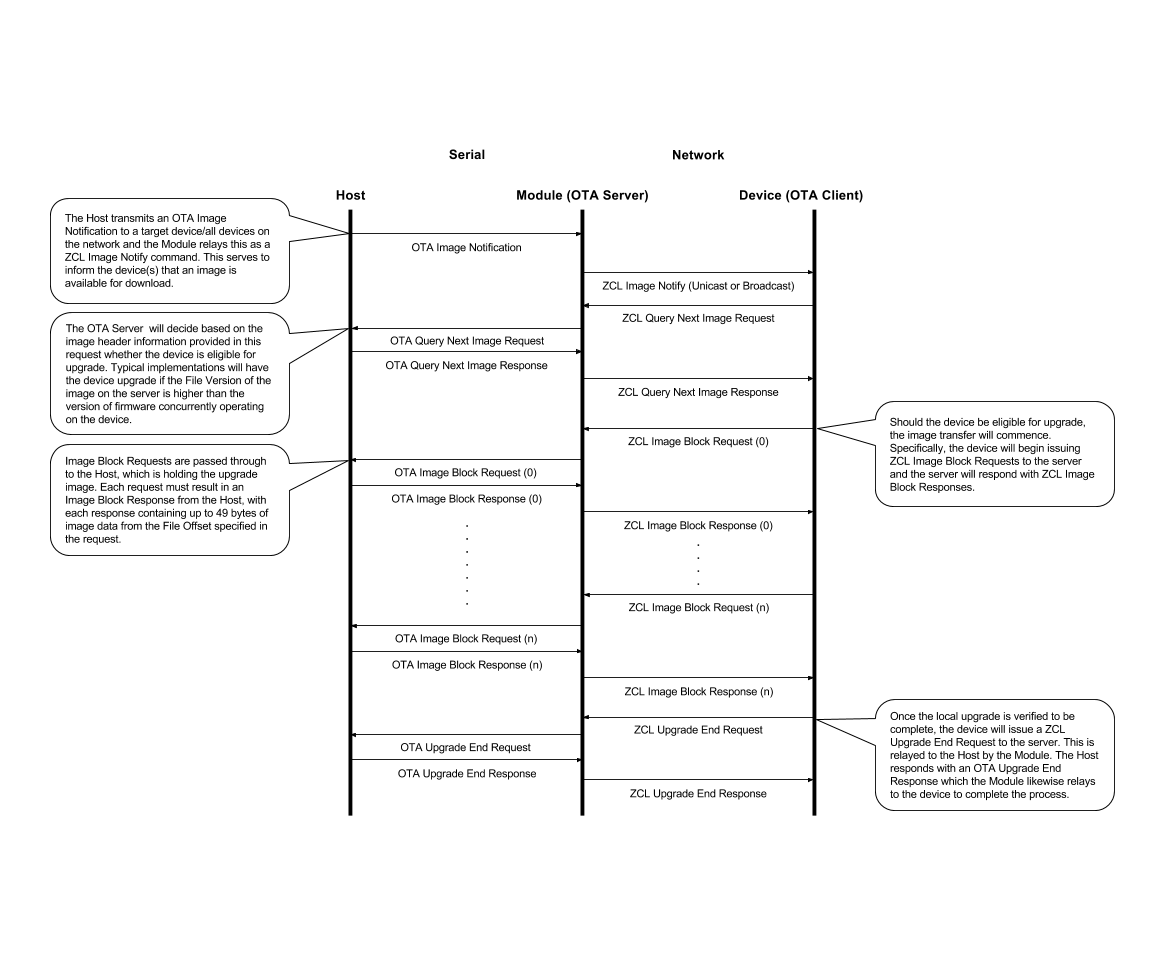
The following sequence diagram details a successful OTA Upgrade from the perspective of a serial-Host driven OTA Server on the RapidHA application. This is typically implemented on the Gateway. The MMB RHA Desktop can be used as an example during development.
OTA Client
The following sequence diagram details a successful OTA Upgrade conducted between an OTA Server and OTA Client over the network.
.png?version=1&modificationDate=1487102598449&cacheVersion=1&api=v2)
OTA Image Format
The following illustration describes the typical ZigBee OTA image Format for a combined ZigBee SoC/Host Processor image.
The Tag (0) is designated for the ZigBee SoC Image. There are couple other reserved Tags.
The Host Image Tag (N) must fall in the range of 0xF000 - 0xFFFF.
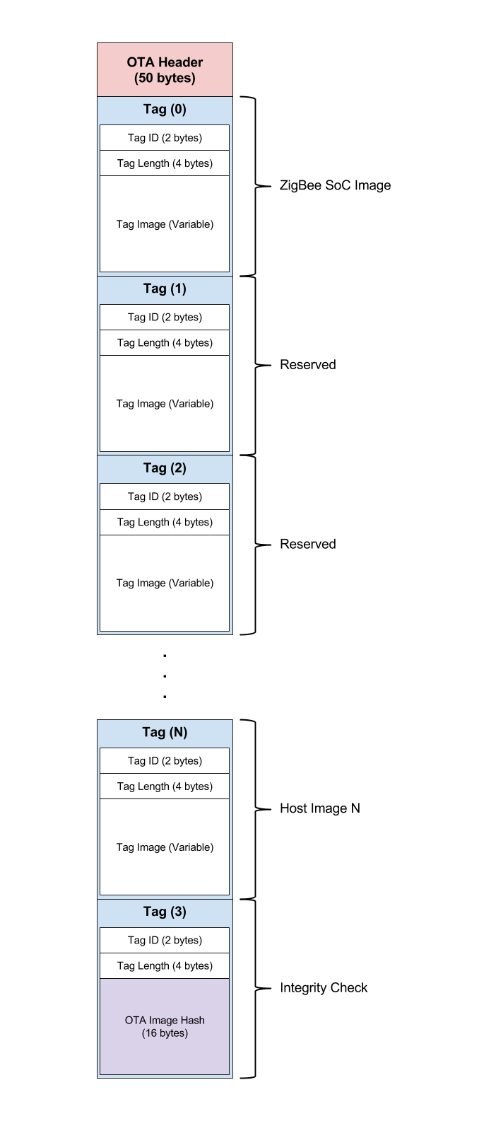
Image Storage and Validation
The ZCL specification for OTA upgrades requires that the ZigBee portion of any downloaded image be validated prior to bootloading and updating the ZigBee SoC. This ensures that a device is not re-programmed with a corrupt image which could brick or otherwise permanently disconnect it from the network.
A typical Host upgrade implementation model adheres to the following:
- The Module is responsible for storing the combined image as it downloads from the OTA Server
- The full image is stored in the External Flash of the Module
- The Module is responsible for the integrity check on the combined image and the Module will only passed to the Host once the integrity check is successful.
- The Host retains the option to perform further integrity checks or decryption on its portion of the image once retrieved from the Module
Host Upgrade Model
This section describes a typical implementation of a non-passthrough model, where the combined image is downloaded and validated by the ZigBee SoC and surrounding components (the Module), prior to the Host portion of that image being passed to the Host.
Please note that in the implementation model described below, the term vHost is shorthand for Virtual Host. The Virtual Host is a thin application layer residing on the standard RapidHA serial interface and serves to expand that interface for custom integration purposes.
Image Transfer Process (Serial)
Once the Module has downloaded the complete Host Image from the network and performed an integrity check, it will notify the Host that a new host image is available. The Host is required to implement a basic serial state machine to retrieve the Host portion of the downloaded image from Module.
The sequence of transactions for this model are illustrated below.
![]()
Host Upgrade Serial Frames
The supplementary serial interface for Host serial image transfers is defined in this section.
Primary and Secondary Headers
Primary Header | Enum |
|---|---|
HOST_BOOTLOAD_HEADER | 0xB1 |
Secondary Header | Enum | Sent by Host/Module |
|---|---|---|
HOST_NEW_IMAGE_AVAILABLE | 0x00 | M |
QUERY_HOST_IMAGE_REQUEST | 0x01 | H |
QUERY_HOST_IMAGE_RESPONSE | 0x02 | M |
IMAGE_BLOCK_REQUEST | 0X03 | H |
IMAGE_BLOCK_RESPONSE | 0X05 | M |
UPGRADE_END_REQUEST | 0x06 | H |
UPGRADE_END_RESPONSE | 0x07 | M |
HOST_BOOTLOAD_READY_REQUEST | 0x10 | M |
HOST_BOOTLOAD_READY_RESPONSE | 0x11 | H |
HOST_FINISHED_BOOTLOADING | 0x13 | H |
| HOST_FINISHED_BOOTLOADING_ACK | 0x14 | M |
HOST_BOOTLOAD_ABORT | 0x20 | H |
Host Bootload Ready Request
The Host Bootload Ready Request frame is sent from the Module to the Host. It queries the Host to determine if it is in a state suitable to ota transfer of host image. This serial frame is sent from the Module at the time when the Module is ready to process with downloading the host portion of the combined OTA file. It gives the Host processor the earliest chance to abort the ZigBee OTA download process if it sees fit.
This frame has no payload.
Host Bootload Ready Response
The Host Bootload Ready Response frame is sent from the Host to the Module in response to a Host Bootload Ready Request. It gives the Host processor the earliest chance to abort the ZigBee OTA download process if it sees fit.
Payload
Octets | 1 |
|---|---|
Data Type | Unsigned 8-bit |
Field Name | Ready Flag |
Ready Flag Enumerations
Enum | Ready Flag |
|---|---|
0x00 | Ready |
0x01 | Not Ready |
Host New Image Available
The Host New Image Available frame is sent from the Module to the Host. It notifies the Host that a new Host image is available. The Host is expected to enter bootload mode on reception of this command.
Payload
Octets | 2 | 4 | 1 | 1 | Variable |
|---|---|---|---|---|---|
Data Type | Unsigned | Unsigned | Unsigned | Unsigned | Octet |
Field Name | Tag ID | Image Size | Image Version | Image Version | Image Version |
Query Host Image Request
The Query Host Image Request frame is sent from the Host to the Module. It serves to query the Module for the latest available Host image, as distinguished by the given Tag ID.
Payload
Octets | 2 | 1 | 1 | Variable |
|---|---|---|---|---|
Data Type | Unsigned 16-bit | Unsigned 8-bit | Unsigned 8-bit | Octet |
Field Name | Tag ID | Image Version | Image Version | Image Version |
Query Host Image Response
The Query Host Image Response is sent from the Module to the Host in response to a Host Image Request. It conveys the available Host image associated with the given Tag ID, along with additional image header data.
Payload(s)
Status: Success
Octets | 2 | 1 | 4 | 1 | 1 | Variable |
|---|---|---|---|---|---|---|
Data Type | Unsigned | Unsigned | Unsigned | Unsigned | Unsigned | Octet |
Field Name | Tag ID | Status: | Image Size | Image Version | Image Version | Image Version |
Status: Invalid Tag ID
Octets | 2 | 1 |
|---|---|---|
Data Type | Unsigned 16-bit | Unsigned 8-bit |
Field Name | Tag ID | Status: Invalid Tag ID (0x98) |
Status: Invalid Image
Octets | 2 | 1 |
|---|---|---|
Data Type | Unsigned 16-bit | Unsigned 8-bit |
Field Name | Tag ID | Status: Invalid Image (0x96) |
Image Block Request
The Image Block Request frame is sent from the Host to the Module. It facilitates the Host retrieving the Host image data from the Module, block-by-block.
Payload
Octets | 2 | 4 | 1 |
|---|---|---|---|
Data Type | Unsigned 16-bit | Unsigned 32-bit | Unsigned 8-bit |
Field Name | Tag ID | File Offset | Maximum Data Size |
Image Block Response
The Image Block Response frame is sent from the Module to the Host in response to an Image Block Request. It should be noted that the Module will attempt to adhere to the Maximum Data Size specified in the request; however, it is possible that the Module will provide an image block smaller than that requested, as indicated by the Data Size parameter.
Payload(s)
Status: Succes
Octets | 2 | 1 | 4 | 1 | Variable |
|---|---|---|---|---|---|
Data Type | Unsigned 16-bit | Unsigned 8-bit | Unsigned 32-bit | Unsigned 8-bit | Octet |
Field Name | Tag ID | Status: | File Offset | Data Size | Image Data |
Status: Invalid Tag ID
Octets | 2 | 1 |
|---|---|---|
Data Type | Unsigned 16-bit | Unsigned 8-bit |
Field Name | Tag ID | Status: Invalid Tag ID (0x98) |
Status: Invalid Offset
Octets | 2 | 1 |
|---|---|---|
Data Type | Unsigned 16-bit | Unsigned 8-bit |
Field Name | Tag ID | Status: Invalid Offset (0x87) |
Status: Invalid Image
Octets | 2 | 1 |
|---|---|---|
Data Type | Unsigned 16-bit | Unsigned 8-bit |
Field Name | Tag ID | Status: Invalid Image (0x96) |
Upgrade End Request
The Upgrade End Request frame is sent from the Host to the Module, after the Host has downloaded the complete image from the Module and performed any additional image verification. In particular, the Host should verify the size of the image received.
The frame serves to notify the Module that the Host is ready to bootload and upgrade. The Host should not commence the bootload until it receives an Upgrade End Response from the Module.
Payload
Octets | 2 | 4 |
|---|---|---|
Data Type | Unsigned 16-bit | Unsigned 32-bit |
Field Name | Tag ID | Image Size |
Upgrade End Response Command
The Upgrade End Response frame is sent from the Module to the Host in response to an Upgrade End Request. It serves to notify the Host that it may bootload and upgrade.
Payload
Octets | 2 | 1 |
|---|---|---|
Data Type | Unsigned 16-bit | Unsigned 8-bit |
Field Name | Tag ID | Upgrade Flag |
Upgrade Flag Enumerations
Enum | Upgrade Flag |
|---|---|
0x00 | Upgrade Allow |
0x96 | Invalid Image |
0x98 | Invalid Tag ID |
Host Finished Bootloading
The Host Finished Bootloading frame is sent from the Host to the Module after the Host has completed bootload and upgrade and has re-entered its application state. It is recommended that the Host wait a 2-5s after completion before transmitting serial commands to the Module.
Payload
Octets | 2 |
|---|---|
Data Type | Unsigned 16-bit |
Field Name | Tag ID |
Host Finished Bootloading Acknowledge
The Host Finished Bootloading Acknowledge frame is sent from the Module to the Host. The purpose of this serial frame is to acknowledge to the Host that the Module has received the Host Finished Bootloading.
Payload
Octets | 1 |
|---|---|
Data Type | Unsigned 8-bit |
Field Name | Status |
Status Enumerations
Enum | Ready Flag |
|---|---|
0x00 | Success - Enter Module Bootloader for Self Bootloading |
0xXX | add error status as needed in the future |
Host Bootload Abort
The Host Bootload Abort frame is sent from the Host to the Module. It serves to abort the bootload/upgrade in progress. The Host firmware can fill in their own abort error code for debugging purpose. So that the Host Processor Abort reason can be observed via the serial log.
Payload
Octets | 1 |
|---|---|
Data Type | Unsigned 8-bit |
Field Name | Abort Reason |
Abort Reason Enumerations
Enum | Reason | Details |
|---|---|---|
0x00 | Abort Reason | Host Processor to fill in as many abort/error code as needed |
0xXX |
Module Reboot Reason Serial Frame
The new Serial Frame for the ZigBee firmware to indicate the reboot reason is defined in this section.
Primary and Secondary Headers
Primary Header | Enum |
|---|---|
UTILITY_HEADER | 0x55 |
Secondary Header | Enum | Sent by Host/Module |
|---|---|---|
MODULE_REBOOT_REASON | 0x11 | M |
Module Reboot Reason
The Module Reboot Reason frame is sent from the Module to the Host during Module Boot up. It gives the reason why the Module Firmware is rebooted as well as the current version that is running on the Module firmware.
This frame lets the Host knows that the ZigBee Module has been rebooted.
Payload
Octets | 1 | 1 | Variable |
|---|---|---|---|
Data Type | Unsigned 8-bit | Unsigned 8-bit | Octet |
Field Name | Status | Version Length | Version |
Status Enumerations
Enum | Status |
|---|---|
0x00 | Non Bootload Power Cycle |
0x01 | Bootload Upgrade Success |
0x02 | Bootload Upgrade Failure |
0x03 | Host Serial Upgrade in Progress |
Host Processor Bootload and Upgrade
The Host will be responsible for the bootload and upgrade of itself and any child processors. During the Host bootload phase, it is recommended that the Host first backup its existing image in a suitable memory partition, typically on external flash. The Host will then retain the capacity to switch back to this image in case the upgrade does not succeed for any reason.
Q/A
| Question | Answer | |
|---|---|---|
| What is the max size of all combined Host Images that can be supported? | 640 kB | |