There are four startup scenarios requiring that requires synchronization between the Host and Module:
...
Upon startup, the Host must issue the the Host Startup Ready command command. On receiving the the Startup Sync Request command command will be sent from the Module , to the Host(see figure 1 for an alternate sequence). The Host may then enter the Startup Synchronization sequence to perform the aforementioned configuration of the endpoints, clusters and attributes. The Startup Sync Request command from the Module will include information on which application configurations may be restored from external flash and which the Host must reconfigure.
The Host completes the phase by sending the the Startup Sync Complete command command to the Module.
This page provides illustrated examples of the Startup Synchronization sequence.
...
The diagrams in this section illustrate the Startup Synchronization sequence.The following
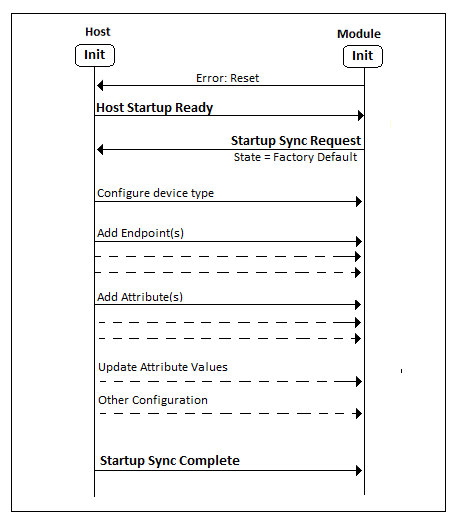
figure Figure (1) illustrates the expected Startup Synchronization sequence following the first power up of the Module from its factory default state. In this diagram, the Configuration and Updates phase from the previous figure has been expanded to show key operations performed by the Host.
| Anchor | ||||
|---|---|---|---|---|
|
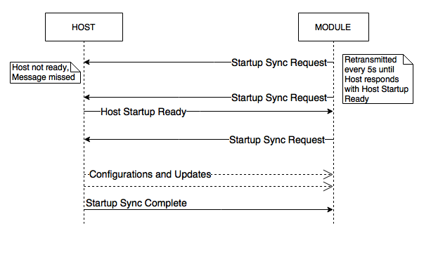
Figure (2) illustrates the sequence when the Module initializes more quickly than before the Host (described in scenario (2)). The Module retries the In this scenario the Module starts sending Startup Sync Request periodically(every 5 seconds) to ensure that the Host receives the message even if the Host starts up slower than the Module. You can see in the figure, the Host Startup Ready command is sent after the Startup Sync Request. The Module is required to send a final Startup Sync Request after receiving the Host Startup Ready command. The Host can now start the Configuration sequence.
Upon the Host completing synchronization (by performing all necessary configurations and updates) it will transmit the Startup Sync Complete command to the Module, at which point the Module will initiate the full application, i.e., commence network activities, etc.
| Anchor | ||||
|---|---|---|---|---|
|
...
Figure 2: Startup Synchronization Request Retries
The next figure illustrates the expected Startup Synchronization sequence following the first power up of the Module from its factory default state. In this diagram, the Configuration and Updates phase from the previous figure has been expanded to show key operations performed by the Host.
...
The next figure
Figure (3) illustrates the Startup Synchronization sequence after power up of a configured Module (i.e., subsequent to the state achieved in the previous previous figure 2). The application device type does not need to be defined as it is preserved in non-volatile memory. All configured endpoints, clusters and attributes are stored in volatile memory and must be re-configured after any soft or hard reset of the Module.
| Anchor | ||||
|---|---|---|---|---|
|
The next figure
Figure (4) is a flow chart of how the Host may implement its startup sequence to synchronize with the Module.
| Anchor | ||||
|---|---|---|---|---|
|
...
Figure 4: Host Startup Configuration Flow Chart


