Summary
Many lighting vendors have recognized that wireless controls systems such as Daintree ControlScope and other ZigBee-based platforms can add significant value to their products. However, it can be difficult to get to market quickly with a robust and reliable solution that meets the requirements of these platforms. To that end, MMB has created the RapidHA Lighting firmware to run on our world-class RapidConnect hardware, providing out-of-the-box compatibility with Daintree ControlScope and other systems based on the ZigBee HA 1.2 specifications.
MMB is able to provide RapidConnect ZigBee modules that are loaded with firmware that will automatically join a Daintree ControlScope or ZigBee HA 1.2 network as a Dimmable Light device. The RapidConnect module can interface with an LED driver via UART or PWM to set the appropriate brightness level or on/off state in response to commands from the Daintree WAC or HA 1.2 coordinator. In other words, MMB’s RapidHA Lighting solution allows lighting OEMs to set up a functional wireless lighting demonstration as soon as they are able to wire up the module to their hardware!
The pages below provide more information about RapidHA Lighting hardware/firmware offering:
Pinout
The following pinout describes the other key features in the firmware. The Z357PA40 module pad numbers are shown in brackets:
- PB3 (Pad 5): Relay Control
- PB4 (Pad 6): PWM signal (can be converted to 0-10V with an additional circuit)
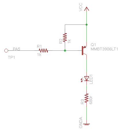
- PA5 (Pad 9): Network Status Indicator LED **A transistor circuit is required to ensure that this pin is held high at startup. This pin assignment will be changing. See the note in the "PA5 Protection Circuit" section below.
- PA6 (Pad 16): Button for factory reset (by driving this pin low for >5 seconds)
The following pins are also used by the firmware for testing and debugging purposes:
PA5 Protection Circuit:
Recent space activity
| Recent updates | ||||||||
|---|---|---|---|---|---|---|---|---|
|
Space contributors
| Contributors | ||||||||||
|---|---|---|---|---|---|---|---|---|---|---|
|