Configuration of Device Types
The Module provides facilities for the Host to define and configure the application ZigBee logical device type and IEEE functional device type as well as support for specific endpoints, clusters and attributes.
Device Type
The Host may issue the Device Type Write command to the Module in order to configure the IEEE functional device type.
The Module may be configured to behave as either a Full-Function Device (FFD) or Reduced-Function Device (RFD). An FFD has facilities for routing network messages, while an RFD may only join a network as a non-routing End Node.
Sleepy Devices
Sleepy Devices require a more in depth look. Sleepy device behaviour should be well understood before developing your solution.
If the Host configures the Module as an RFD, it may additionally configure the Module to serve as either a non-sleepy or sleepy end device, with the latter configuration serving to conserve power should the given device be battery powered or otherwise consumption-sensitive.
Sending a serial frame will wake up the Module if it is sleeping. The Module will then stay awake for 5 milliseconds so the Host will have to send its desired serial frame within this period. One way to ensure the Module is awake to receive a command is to send the same frame twice within one second of each other. The first frame will be used to wake up the Module and the second frame will be processed.
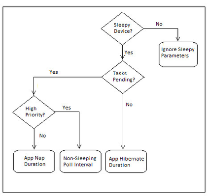
For sleepy devices, there are four additional parameters that control the operation of the device. The parameters are:
- App Nap Duration
- App Hibernate Duration
- Non-Sleeping Poll Interval
- Poll Fail Trigger Rejoin Duration
The flow chart in the following figure illustrates how the parameters are chosen in a sleepy device.
Sleepy Parameters Flow Chart
Version 1.2 of the Home Automation Public Profile introduces the Poll Control cluster. This cluster provides a way to make the Module responsive on the network for a specific amount of time. In other words, a sleeping device may mostly remain in a low power consumption mode, but will still be able to respond promptly when asynchronous communication is desired. This is accomplished by means of differing poll rates, which is the frequency of MAC data requests from child to parent.
The Poll Control cluster has two attributes (ShortPollInterval and LongPollInterval) that are used to alter the poll rate of the Module. The sleepy write commands (Sleepy Parameters Write CMD and Sleepy Hibernate Duration Write CMD) can also alter the poll rate of the Module. Both the cluster attributes and the sleepy write commands are used to change the value of the App Hibernate Duration parameter. It is this parameter that primarily determines the sleepy behavior of the Module. The flow chart shown below illustrates how the App Hibernate Duration parameter interacts with the Poll Control cluster.
App Hibernate Duration Parameter/Poll Control Cluster Relationship
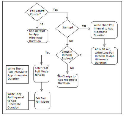
Managing when the Module is in Fast Poll Mode is the sole reason for having the Poll Control cluster. The flow chart above shows that the Module goes into this responsive mode at startup and when the server cluster’s attribute, Check-inInterval, indicates it is time to ask any client-side clusters bound to the server if Fast Poll Mode is desired.
Please note that calling the serial protocol commands Sleepy Parameters Write CMD or Sleepy Hibernate Duration Write CMD may alter the poll rate of the Module but will not affect the Poll Control cluster attributes.
Sleep Control
RapidHA v1.7.5 introduces new Serial Protocol commands that allow more control over the sleep/wake functionality of sleepy device types. Please see this tutorial for instructions on exercising the RapidHA serial interface for the new sleep control frames and to gain a better understanding of how to utilize the sleep control commands.
Module Wakeup Behaviour
When a module is configured as a Sleepy Device it will switch between an awake and an asleep state. While the module is sleeping it will idle TX/RX and consume relatively little power. This is useful for products that are power sensitive, such as battery powered end devices.
When the module wakes up it will poll it's parent for messages and also initialize it's peripherals. To alert the Host application that it is waking up, the module will send a burst of FFs serially to the Host application. It is important to note that these bytes will not follow the standard serial protocol start of frame format ( F1 xx xx ....). Customers implementing their own frame parsing should deal with these FFs accordingly.
To implement a more robust frame parser it is good practice to develop a parser that adheres to the RHA serial protocol format, payload length and checksum while gracefully handling bytes that do not match these criteria.
ZigBee Logical Device Types
The ZigBee logical device types and corresponding IEEE functional device types are shown in the following table.
Device Types
ZigBee Logical Device Type | IEEE Functional Device Type |
|---|---|
Coordinator | Full-Function Device, Non-Sleepy |
Router | Full-Function Device, Non-Sleepy |
End Device | Reduced-Function Device, Non-Sleepy |
Sleepy End Device | Reduced-Function Device, Sleepy |
It should be noted that coordinators and routers share the same IEEE functional device type. The ZigBee logical device type will be determined when the application is prompted to either Form a network (become a coordinator) or Join a network (become a router).
Endpoints and Clusters
The Host may issue the /wiki/spaces/SPRHA17/pages/37093548 command to the Module to configure application support for an endpoint and related clusters operating on that endpoint. The application will support up to 32 endpoints and up to 100 clusters total across all active endpoints.
When the Host adds a cluster for which the application already has preconfigured support (i.e. Basic, Identify, On/Off, Control4 Large Network Support, etc.), the application automatically adds all mandatory attributes associated with that cluster and enables default message processing for the added cluster.
For example, if the Host adds the On/Off server cluster to a given endpoint, the application will automatically add the mandatory On/Off attribute to that cluster. Furthermore, the application will process incoming messages directed to that cluster such that the Host is kept notified of any change of state relating to its mandatory attribute (i.e., the On/Off attribute). In the case of this example, the notification is done via the On/Off State Update command.
The application currently provides automated support for the following clusters:
Basic Server
Identify Server/Client
Commissioning Server
Time Server/Client
Power Configuration Server
Alarms Server
On/Off Server/Client
Level Control Server/Client
Thermostat Server
Thermostat UI Configuration Server
Fan Control Server
Doorlock Server
Poll Control Server/Client
IAS Zone Server
IAS ACE Server
IAS Warning Device Server
Ballast Configuration Server
Groups Server/Client
Scenes Server/Client
OTA Upgrade Server/Client
Diagnostics Server
Control4 Large Network Support Client
Attributes
After adding the desired endpoints and clusters, the Host may issue the Add Attributes to Cluster command to the Module in order to add support for attributes on the specified cluster.
The application will support up to 300 attributes in sum total across all clusters.
When the Host adds an attribute to a cluster, the application will initialize that attribute with a default value corresponding to its given Data Type, as described in the following table. Please note that some of the default values are also invalid. This is to indicate that the value is unknown; that is, not yet set by the Host.
The Host may also configure the given attribute with any valid value, by issuing the Attribute Write command. Furthermore, the Host may query the given attribute’s value by issuing the Attribute Request command.
Attribute Data Types and Default Values
Attribute Data Type | Default Value |
|---|---|
Genera Data (8, 16, 24, 32, 40, 48, 56, 64-bit) | All zeros (i.e., 0x00, 0x0000, etc.) |
String | Empty string |
Boolean | False |
Bitmap | All 0’s |
Unsigned Integer (8, 16, 24, 32, 40, 48, 56, 64-bit) | All 1’s (i.e., 0xFF, 0xFFFF, etc.) |
Signed Integer (8, 16, 24, 32, 40, 48, 56, 64-bit) | Mot significant bit set to 1 (i.e., 0x80, 0x8000, etc.) |
Enumeration (8, 16-bit) | All 0’s |
Legal Notices
Copyright © 2017 MMB Networks, Inc. All rights reserved.
Confidential materials prepared and delivered by MMB Networks for receipt and review only by any partner subject to a valid and enforceable MMB Networks confidentiality agreement. Any receipt, review, or misuse of any of the content exchanged hereunder by any party not a party to this confidential exchange shall be subject to any and all rights available under the law. All rights, title and interest to the materials shall remain with MMB Networks.
Any suggestions provided to MMB Networks with respect to MMB Networks' products or services shall be collectively deemed “Feedback.” You, on behalf of yourself, or if you are providing Feedback on behalf of your employer or another entity, represent and warrant that you have full legal authority to bind such entity to these terms, agree to grant and hereby grant to MMB Networks a nonexclusive, perpetual, irrevocable, royalty free, worldwide license to use and otherwise exploit such Feedback within any MMB Networks products and services.