Getting Started - Day 1 Demo Setup
- Luke Tutty (Unlicensed)
- Tracy W (Deactivated)
- Alireza Motamed
- Doug Alguire (Deactivated)
Introduction
The goal of this document is to walk users through setting up their RapidConnect Lighting & Sensor Development Kit, with instructions on network management, peripheral control and attribute reporting.
This Guide uses the RapidConnect Desktop Application for demonstrating the RapidConnect Lighting & Sensor Development kit features. RapidConnect Desktop is currently in Beta. Please contact info@mmbresearch.com to access RapidConnect Desktop Beta.
Definitions of Terms and Acronyms
You can find a full list of useful Zigbee terms and acronyms in the MMBNetworks Zigbee 101 guide.
Sections
Pre-Requisites
RapidConnect USB Drivers
The first step required to get your Demo Kit up and running is to install the necessary RapidConnect USB Stick Drivers for your RapidConnect Lighting & Sensor Evaluation Board and RapidConnect USB Stick.
RapidConnect USB Stick Drivers for Windows(32/64 bit) and OS x.
RapidConnect Desktop Application
MMB Networks supplies the RapidConnect Desktop as a ready-to-use Host Application that gives users the ability to manage a Zigbee network and to interact with the RapidConnect Lighting & Sensor Evaluation Board.
Day-1 Demo
Hardware Setup
Open RapidConnect Desktop
To start the Day-1 Demo, connect your devices via USB to the machine on which you have installed RapidConnect Desktop.
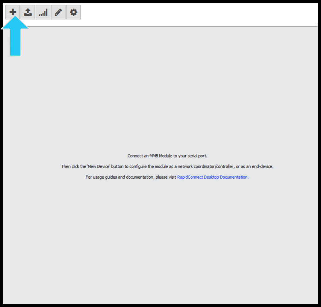
Once the RapidConnect Lighting & Sensor Evaluation Board and the RapidConnect USB Stick are connected to the machine and device driver installation is complete, open the RapidConnect Desktop Application. The start page is shown below.
.png?version=1&modificationDate=1571744652400&cacheVersion=1&api=v2&width=503&height=480)
Configure RapidConnect USB Stick
Select the ‘New Device’ button from the menu.
Select the MMB RapidConnect USB Stick from the available module list. The EUI64 will match the EUI64 printed on the USB Stick.
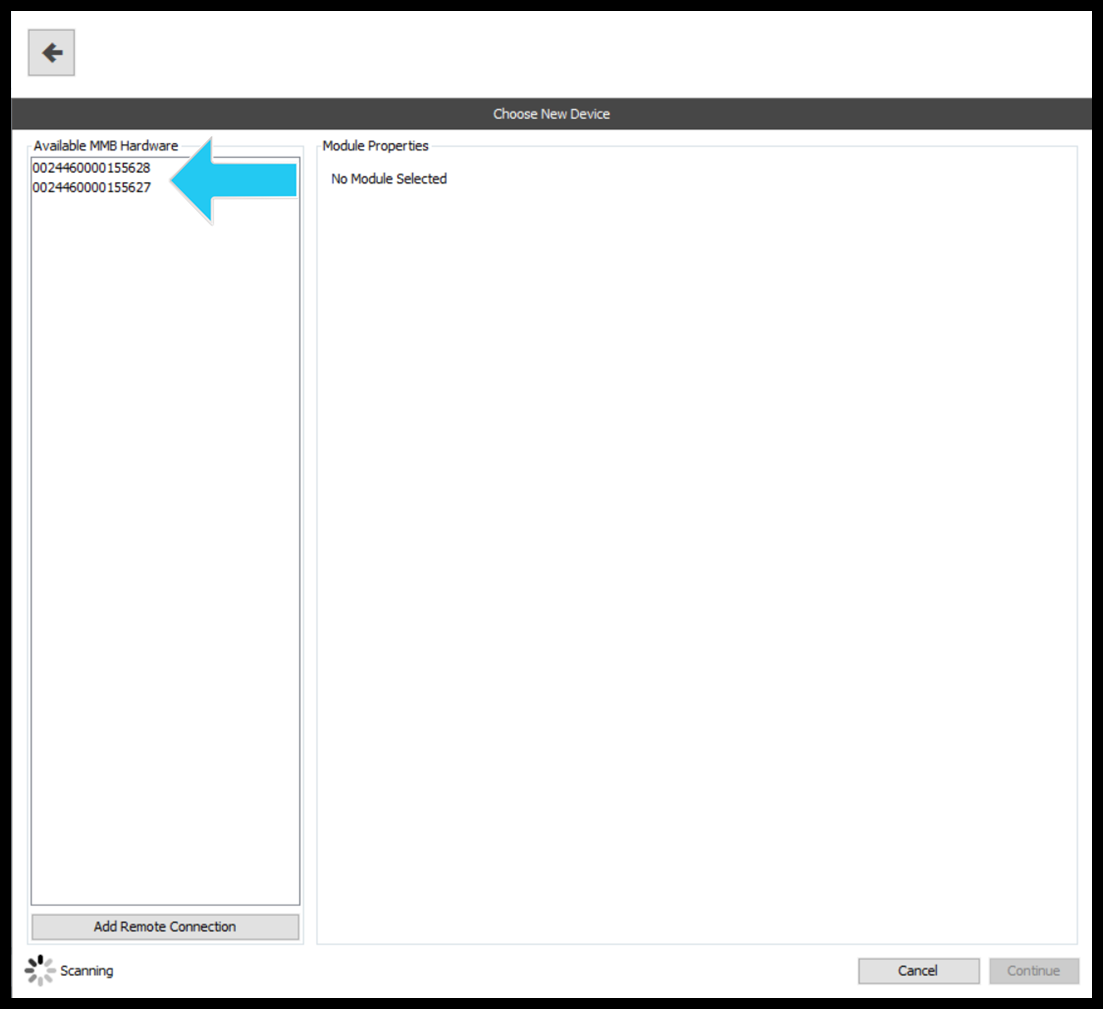
Once the device is selected, you will be able to see certain details about it such as its current firmware version, hardware type and configuration.
At this point, we want to configure this device as the coordinator of our Zigbee network.
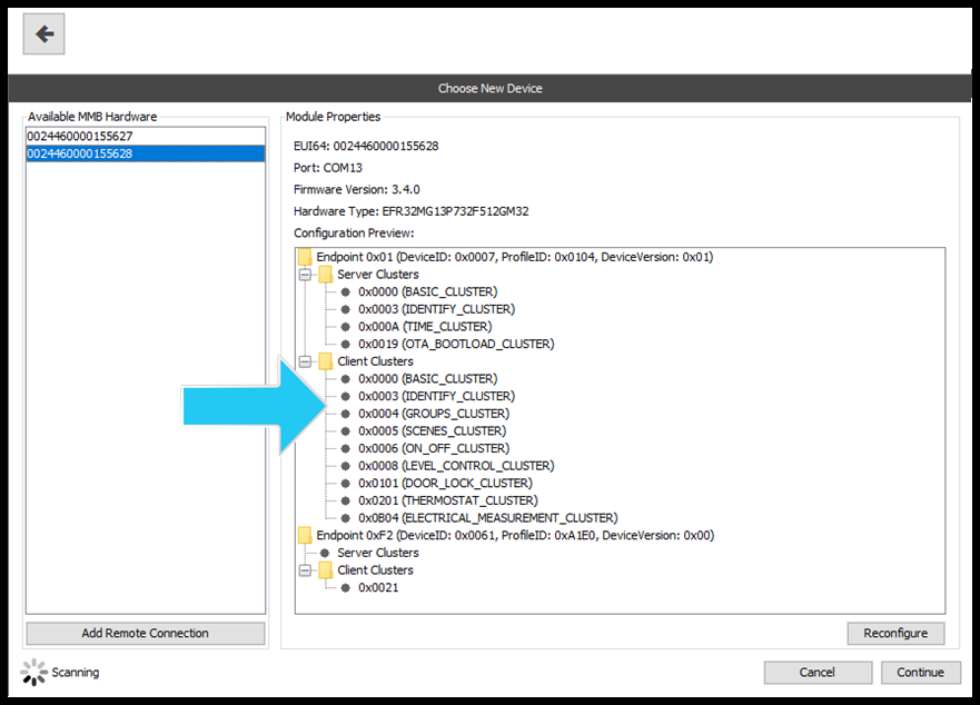
If the device does not have a previous configuration the ‘Configuration Preview’ window may be empty
Click on the ‘Reconfigure’ button.
RapidConnect Desktop gives user the ability to configure their devices using pre-set configurations such as ‘Combined Interface Coordinator’, ‘Power Outlet’ and ‘Door Lock’.
These pre-set configurations serve to set the device up with all the necessary Clusters, Endpoints and Attributes required for fulfilling its role on the network.
It also gives the user the ability to create their own device configuration (a topic covered in our general RapidConnect documentation).
In the next window, expand the dropdown box, select ‘Combined Interface Coordinator’ and then select 'OK'. The Device will now be configured to be the network coordinator.
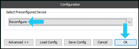
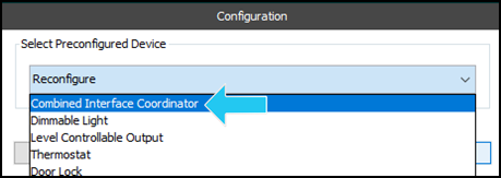
Click the 'OK' button
The desktop will now run through the configuration process and configure the USB stick with the selected configuration.
Once the device has finished configuring, the 'Network Management' page will open. This page allows you to configure and manage the device network such as forming a network, joining a network and setting link keys.
The figure below shows the 'Network Management' page.
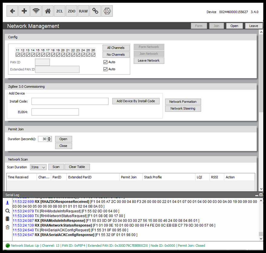
Before we go any further, we will open an interface to the RapidConnect Lighting & Sensor Evaluation Board.
Configure RapidConnect Lighting & Sensor Evaluation Board
The next step is getting the Evaluation Board to join to your newly formed network. You will then be able to interact with your Evaluation Board over the network.
The demo board comes pre-configured with the following parameters:
| Endpoint 0x16 | Endpoint 0x17 | Endpoint 0x18 | |
|---|---|---|---|
| Server Clusters |
|
|
|
| Client Clusters |
|
Click on the ‘New Device’ button from the top menu.
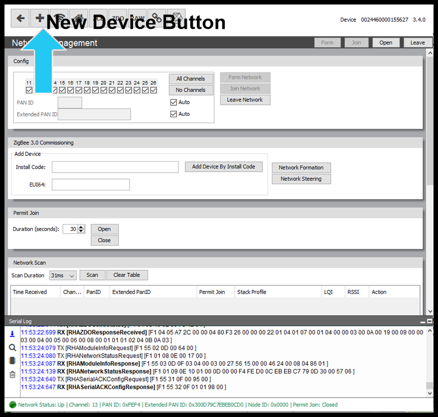
This will create a new instance of the RapidConnect Desktop and will allow you to interface with your Evaluation Board and to join the previously configured coordinator once the network has been formed.
Select the Evaluation Board from the module selection window.
Once the device is selected the Evaluation Board properties and configuration preview will be shown. The device will be auto configured and there is no need to reconfigure or select a specific configuration.
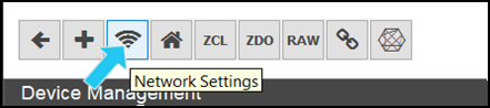
Click the ‘Continue’ button to open the 'Network Settings' page.
Network Control
Form Network
Once the devices are configured return to the RapidConnect Desktop instance of the coordinator and go to the ‘Network Settings’ page.
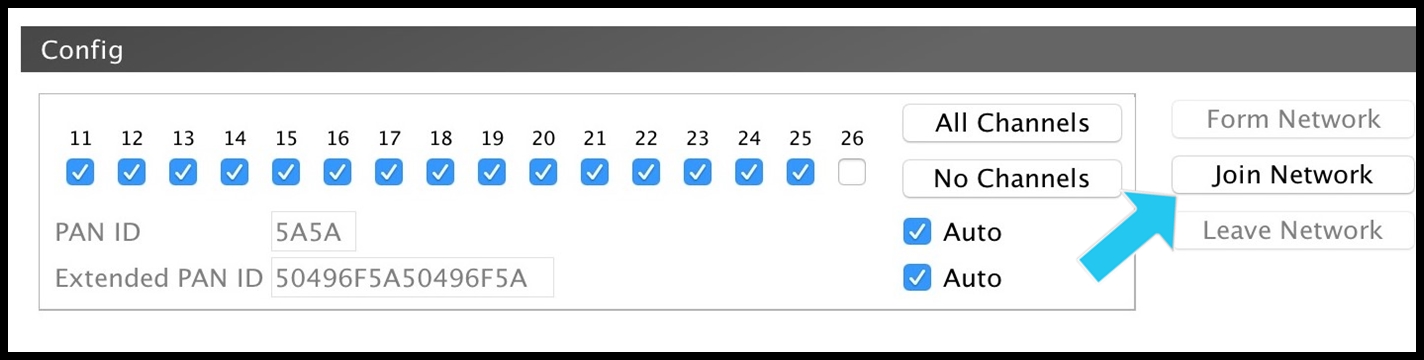
Here you will be presented with options for configuring your network.
This guide will assume that default values are used for the APS Link Key parameters and the 'Auto' options are checked for PAN ID and Extended PAN ID.
The 'Auto' options will generate random values for both PANID and Extended PAN ID.
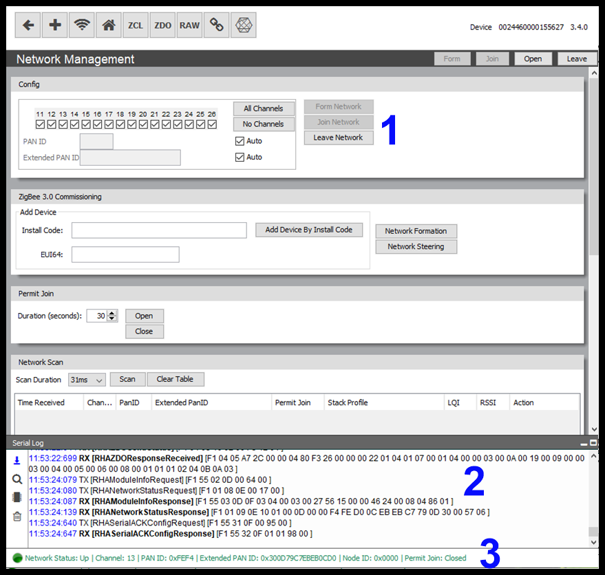
The Network Settings page can broken down into the following components:
- Network Configuration Parameters
- Network Actions
- Permit Join Window
- Zigbee 3.0 Commissioning
- Network Scan
- Latency
- APS Link Key
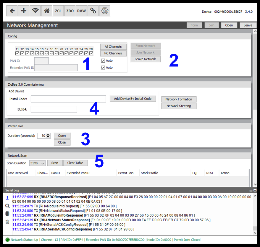
To form a network the user need only to click the ‘Form Network’ button, as seen in the image above.
Once clicked the RapidConnect Desktop application will issue the necessary commands to the coordinator USB stick in order to form a network with the selected parameters. If multiple channels are selected, the channel with the least amount of RF ‘noise’ will be chosen. Alternatively, the user can select a specific channel on which to form a network.
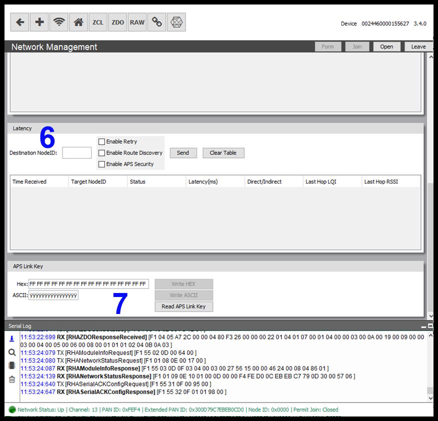
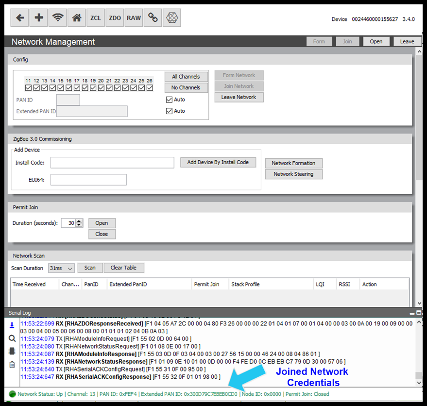
Once network forming is complete RapidConnect Desktop will enable the 'Leave Network' button (1) and show the new network status and network information (3). The ‘Serial Log Viewer’ will also be populated with serial messages sent between the Host (RapidConnect Desktop) and the device (2).
Join Network
To join the Evaluation Board to the newly formed Zigbee network, you must first open the ‘Permit Join’ window of your network.
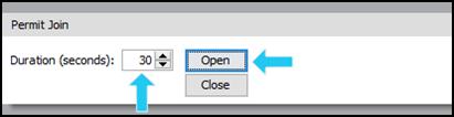
Go to the RapidConnect desktop instance that interfaces to your coordinator. From here open the ‘Network Settings’ window from the top menu bar. Go to the ‘Permit Join’ component and select a duration(e.g. 60 seconds) to open the ‘Permit Join’ window for, click the ‘Open’ button.
The ‘Open Forever’ button will open the permit join window for 248 seconds. Once that duration elapses the permit join duration will automatically reset to 248 seconds, and so on. It is not recommended to use this setting when in an environment with many Zigbee devices as you may get devices that are currently in the ‘Scanning’ network state join our network unintentionally.
The ‘Close’ button sets the permit join duration to 0.
Once the permit join window is open, switch to the RapidConnect Desktop instance for the Evaluation Board. Open the ‘Network Settings’ window from the menu.
Once the ‘Network Settings’ window is open click the ‘Join Network’ button to initialize the joining process.
You will be able to view the frames being sent to and from the module serially via the Serial Log viewer. Once the end device joins a network, the Network Status will be updated and the network configuration will reflect the information of the joined network.
Lighting Control
Send Commands to Evaluation Board
Now that both devices are able to communicate on the Zigbee network you will be able to send commands from the coordinator to control your Evaluation Board.
The 'Remote Devices' page allows you to view the devices on your network along with the Endpoints, Clusters, Attributes and Attribute Values that the device is configured with.
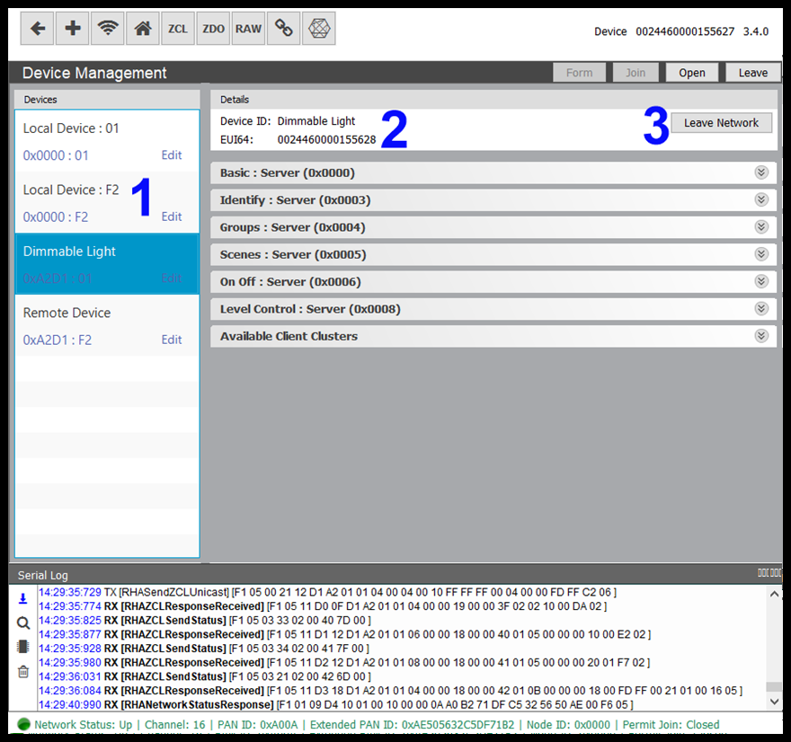
The Remote Devices page can be broken down into the following components:
- Node List: The Node List (1) breaks devices on the network down into their NodeIDs and available Endpoints. Above you will see a LocalDevice(coordinator in this case) and 3 NodeID and Endpoint combinations. 0x9cda above is the node id given to our Evaluation Board and endpoint 16 allows us to control the PWM LED on the device. Select this combination.
- Device Details: When a NodeID is selected the device details sections will show the Device Name (2) and the EUI64 of the selected device. Ensure the EUI64 matches that of your Evaluation Board.
Network Leave: Clicking the 'Leave Network' button will send a request to the currently select device to leave the network. If the selected device is the coordinator, the network will be dissolved.
Expand the On/Off (0x0006) cluster.
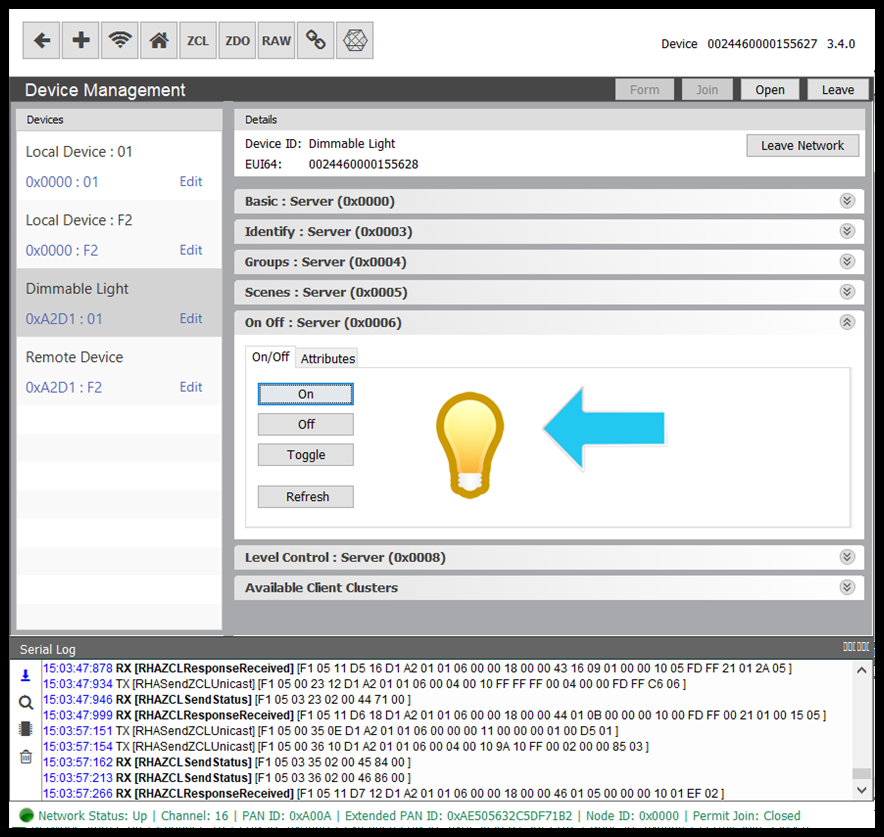
RapidConnect Desktop allows you to interact quickly with clusters by providing a user interface for many of the supported native cluster commands. You can see from the image above that the Desktop provide fast action buttons for sending On, Off and Toggle commands, along with a graphic representation of the current state of the On/Off attribute attribute.
Click on the 'Toggle' button to send a command over-the-air from the coordinator to the Evaluation Board. The state of the PWM LED should change to match the new values.
Expanding the Level/Control (0x0008) server cluster end allows you to send Level control commands to the Evaluation board, allowing you to change the level of the PWM signal.
Sensor Reporting
The RapidConnect Lighting & Sensor Evaluation Board also gives users the ability to demonstrate the attribute reporting from the Occupancy Sensing Cluster (0x0406) and the Illuminance Measurement Cluster (0x0400). To change the state of these attributes, the demo board has the following inputs:
- Button 1 - Ultrasonic Sensor Trigger (Occupancy Sensing Cluster)
- Button 2 - PIR Sensor Trigger (Occupancy Sensing Cluster)
- Dial - Illuminance Measurement Trigger (Illuminance Cluster)
The guide below takes you through configuring attribute reporting for the sensors clusters above.
Occupancy Sensing Cluster
Go to the coordinator instance of the RapidConnect Desktop.
With the network up and the Evaluation Board joined to the network, open the 'Remote Devices' page .
![]()
Select the demo board device and endpoint 17 and expand the server-end cluster 0x0406.
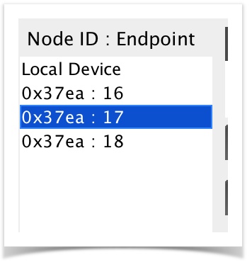
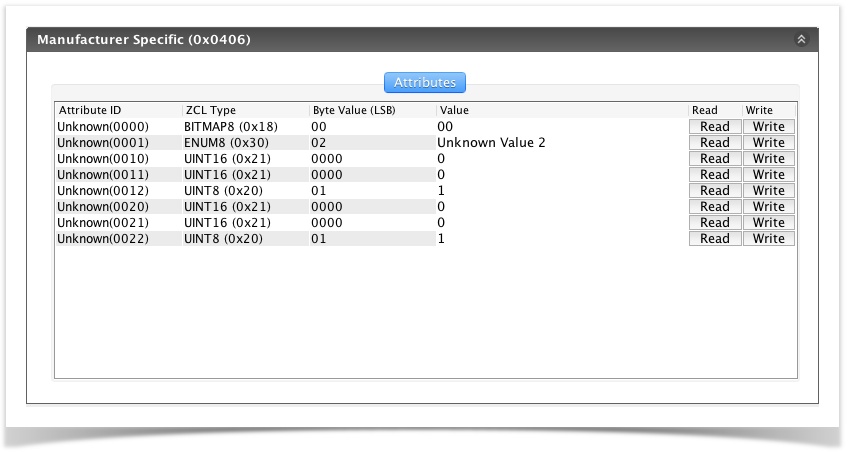
Non-native clusters in the RapidConnect Desktop will be shown in the device cluster list as "Manufacturer Specific". Also attributes details will be shown with the attribute name of unknown.
Create Binding
The first step in enabling attribute reporting is to create a cluster binding.
Open the 'Binding' page from the menu.
![]()
The Binding page is displayed below.
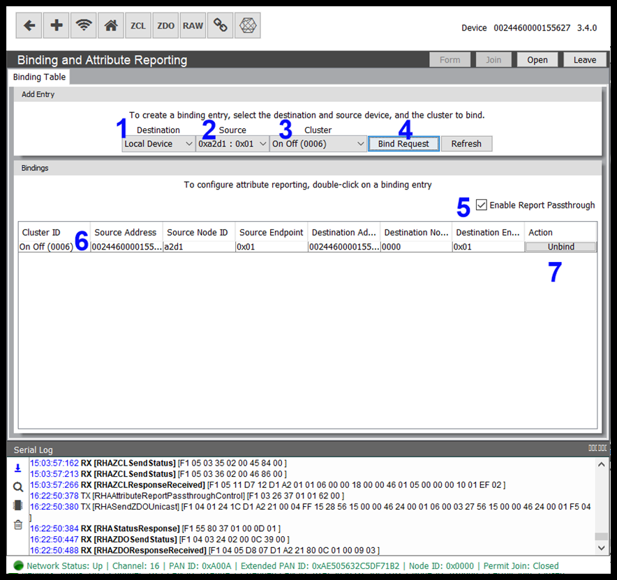
To create a binding follow the steps below.
- Destination: This is the destination of the attribute report, in this case the coordinator. Select 'Local Device'.
- Source: The source of the report, in this case the demo board. Select the NodeID associated with the demo board and endpoint 17.
- Cluster: Once the source endpoint is selected it will populate the cluster list. Select cluster 0x0406 (Occupancy Sensing). Non-native clusters will be displayed as 'Unknown'.
- Send Bind Request: Clicking on the ‘Bind Request’ button will send the request to the Source device which in turn will respond.
- Enable ZCL Passthrough: With RapidHA, attribute reports can be automatically passed up from the module to the Host application (RapidConnect Desktop) by enabling the ‘Attribute Report Passthrough’ control (see RapidHA Serial Protocol for more information). This way attribute reports are passed up to the host application and the application then handles the report. If the passthrough is not enabled, the attribute report will be handled by the module and then discarded.
- Current Bindings: List of current bindings the device has stored in memory
- Unbind: Bindings can be deleted using the 'Unbind' button.
Configure Reporting - ZCL Message
Once the binding stage is complete, we can send a command to configure the attributes we wish to have reported. To do this we send a ZCLUnicast Message from the coordinator to the demo board. The message will contain a Configure Reporting Command (0x06).
Open the ZCL Message Page.
![]()
The ZCL message page can be seen below.
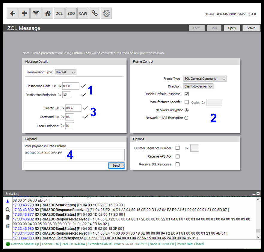
To send a configure reporting command enter the follow parameters below and click the 'Send' Button.
- Message Specific Component
- Transmission Type: Select 'Unicast'.
- Destination Address: Default value.
- Destination Endpoint: 0x17, endpoint 0x17 for Occupancy Sensing Cluster.
- Frame Control Component
- Frame Type: Default value.
- Direction: Default value.
- Disable Default Response: Checked.
- Manufacturer Specific:Default value.
- Frame Control Component
- Cluster: Cluster that attributes are to be reported from, 0x0406 in this case.
- Command ID: 0x06, Configure Reporting command.
- Local Endpoint: 0x01, default endpoint for MMB USB device configured as coordinator.
- Payload
The ConfigureReporting Command has the following fields
Direction Attribute
identifier
Attribute
data type
Minimum reporting interval
Maximum reporting interval
Reportable
change
Timeout
period
0x00 0x0000 (Occupancy) 0x18 (8 bit- Bitmap) 0x0001 0xFFFE not used not used More information regarding the Configure Reporting Command Frame can be found in section 2.4.7.1 of the ZCL Cluster Library Specification.
Once the Configure Reporting Command Frame is sent the Evaluation Board will respond with a Configure Reporting Response Command Frame (see ZCL Cluster Library Specification).
The PIR and Ultrasonic Sensor Buttons will both trigger and change the state of the Occupancy attribute.
Press one of the sensor buttons. If correctly configured the Evaluations Board will report the attribute change over-the-air to the coordinator, the module will pass the attribute report wrapped in a RHAZCLPassthrough frame up to the Host application.
This Passthrough frame will be seen in the 'Serial Log Viewer' of the RapidConnect Desktop Application.
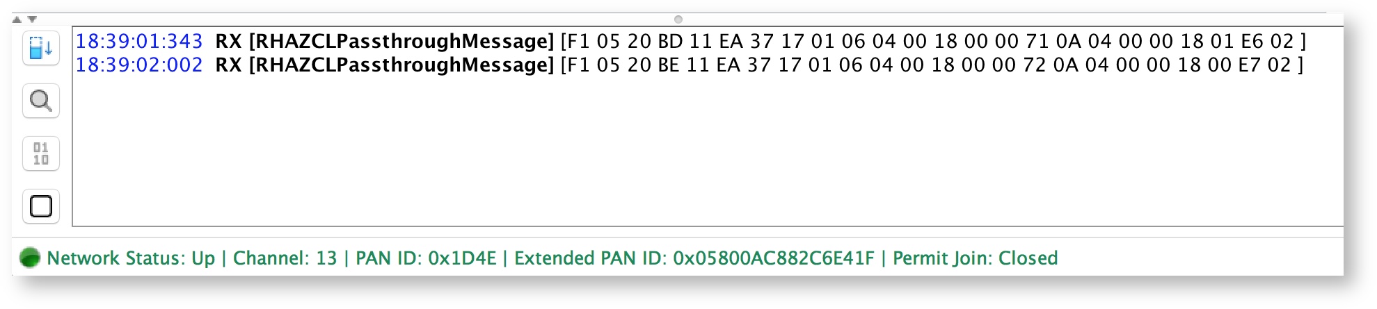
Breakdown of the Passthrough Frame:
Byte Index | Field Name | Value |
|---|---|---|
0,1 | Source Node ID | 0x37EA |
2 | Source Endpoint ID | 0x17 |
3 | Local Endpoint ID | 0x01 |
4,5 | Cluster ID | 0x0406 |
6 | Encryption Level | 0x00 |
7 | Frame Control | 0x18 |
8,9 | Manufacturer Code | 0x0000 |
10 | Transaction Sequence Number | 0x71 |
11 | Command ID | 0x0A (Report Attributes Command) |
12 | Payload Length | 04 |
13..n | Payload | 0x0000 (Attribute Identifier) 0x18 (Attribute Data Type) 0x01 (Attribute Data) Bit 0 specifies the sensed occupancy as follows: 1 = occupied, 0 = unoccupied. |
You can see from the ZCL Passthrough message above that the Occupancy Attribute state changes to 'occupied' once clicked and then back to unoccupied. With a true PIR Device the device typically remains in an occupied state for a much longer duration and then switches to 'unoccupied' once no movement is detected.
Illuminance Measurement Cluster
Attribute reporting for the Illuminance Measurement Cluster will be performed in much the same way as the Occupancy Sensing Cluster, with the following changes.
- Binding
- Select NodeID of demo device and endpoint 0x18
- Select Cluster 0x0400 from dropdown.
- When Sending the ZCLUnicast Message to configure reporting for cluster 0x0400 make the following changes
- Destination Endpoint: 0x18
- Cluster: 0x0400
Payload:
Direction Attribute
identifier
Attribute
data type
Minimum reporting interval
Maximum reporting interval
Reportable
change
Timeout
period
0x00 0x0000 ( MeasuredValue ) 0x21 (16-bit- unsigned integer) 0x0001 0xFFFE 0x0100 not used Reportable Change is required for 'analog' data types. See Table 2-9 in the ZCL Cluster Specification for more information.
Turn the Illuminance Measurement Dial to change the value of the 'MeasuredValue' attribute.
You should see similar output to the following.
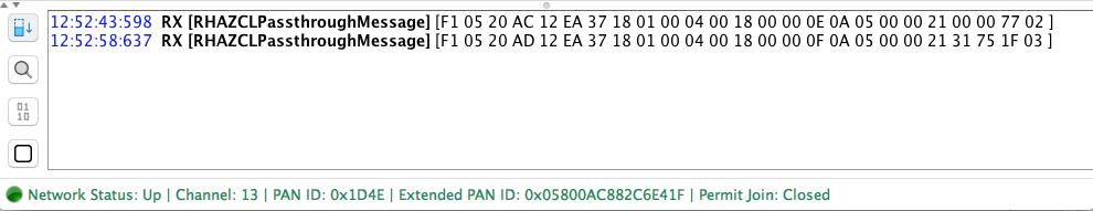
13..n | Payload | 0x0000 (Attribute Identifier) 0x21 (Attribute Data Type) 0x7531 (Attribute Data) 0x7531 is max value |
{style} .wiki-content h1 { font-family: 'Helvetica Neue', sans-serif; font-size: 30px; font-weight: bold; color: #20b6e1; letter-spacing: 1px; line-height: 1; text-align: left; #border-bottom: 1px solid #98bddd !important; } .wiki-content h2 { font-family: 'Helvetica Neue', sans-serif; font-size: 20px; font-weight: normal; color: #00517f; letter-spacing: 1px; line-height: 1; text-align: left; } .wiki-content h3 { font-family: 'Helvetica Neue', sans-serif; font-size: 15px; font-weight: bold; color: #00517f; letter-spacing: 1px; line-height: 1; text-align: left; } .wiki-content h4 { font-family: 'Helvetica Neue', sans-serif; font-size: 15px; font-weight: normal; font-style:italic; color:#00517f; letter-spacing: 1px; line-height: 1; text-align: left; } #title-text{ font-family: 'Helvetica Neue', sans-serif; font-size: 40px; font-weight: 500; letter-spacing: 1px; line-height: 1; text-align: left; } .panel, #content .panel { -moz-border-radius: 5px; -webkit-border-radius: 5px; border-radius: 5px; } .panel .panelHeader { text-align: left; color: #FFFFFF; line-height: 1em; padding: 10px 10px 5px; margin-bottom: 0; background-color: #00517f; -moz-border-radius-topleft: 5px; -moz-border-radius-topright: 5px; -webkit-border-top-right-radius: 5px; -webkit-border-top-left-radius: 5px; border-top-right-radius: 5px; border-top-left-radius: 5px; } {style}
Legal Notices
Copyright © 2020 MMB Networks, Inc. All rights reserved.
Confidential materials prepared and delivered by MMB Networks for receipt and review only by any partner subject to a valid and enforceable MMB Networks confidentiality agreement. Any receipt, review, or misuse of any of the content exchanged hereunder by any party not a party to this confidential exchange shall be subject to any and all rights available under the law. All rights, title and interest to the materials shall remain with MMB Networks.
Any suggestions provided to MMB Networks with respect to MMB Networks' products or services shall be collectively deemed “Feedback.” You, on behalf of yourself, or if you are providing Feedback on behalf of your employer or another entity, represent and warrant that you have full legal authority to bind such entity to these terms, agree to grant and hereby grant to MMB Networks a nonexclusive, perpetual, irrevocable, royalty free, worldwide license to use and otherwise exploit such Feedback within any MMB Networks products and services.