Configuration of Device Types
- Luke Tutty (Unlicensed)
- Philip Emsley (Unlicensed)
The Module provides facilities for the Host to define and configure the application ZigBee logical device type and IEEE functional device type as well as support for specific endpoints, clusters and attributes.
Device Type
The Host may issue the Device Type Write command to the Module in order to configure the IEEE functional device type.
The Module may be configured to behave as either a Full-Function Device (FFD) or Reduced-Function Device (RFD). An FFD has facilities for routing network messages, while an RFD may only join a network as a non-routing End Node.
Sleepy Devices
Sleepy Devices require a more in depth look. Sleepy device behaviour should be well understood before developing your solution.
If the Host configures the Module as an RFD, it may additionally configure the Module to serve as either a non-sleepy or sleepy end device, with the latter configuration serving to conserve power should the given device be battery powered or otherwise consumption-sensitive.
Sending a serial frame will wake up the Module if it is sleeping. The Module will then stay awake for 5 milliseconds so the Host will have to send its desired serial frame within this period. One way to ensure the Module is awake to receive a command is to send the same frame twice within one second of each other. The first frame will be used to wake up the Module and the second frame will be processed.
For sleepy devices, there are four additional parameters that control the operation of the device. The parameters are:
- App Nap Duration
- App Hibernate Duration
- Non-Sleeping Poll Interval
- Poll Fail Trigger Rejoin Duration
The flow chart in the following figure illustrates how the parameters are chosen in a sleepy device.
Sleepy Parameters Flow Chart

Version 1.2 of the Home Automation Public Profile introduces the Poll Control cluster. This cluster provides a way to make the Module responsive on the network for a specific amount of time. In other words, a sleeping device may mostly remain in a low power consumption mode, but will still be able to respond promptly when asynchronous communication is desired. This is accomplished by means of differing poll rates, which is the frequency of MAC data requests from child to parent.
The Poll Control cluster has two attributes (ShortPollInterval and LongPollInterval) that are used to alter the poll rate of the Module. The sleepy write commands (Sleepy Parameters Write CMD and Sleepy Hibernate Duration Write CMD) can also alter the poll rate of the Module. Both the cluster attributes and the sleepy write commands are used to change the value of the App Hibernate Duration parameter. It is this parameter that primarily determines the sleepy behavior of the Module. The flow chart shown below illustrates how the App Hibernate Duration parameter interacts with the Poll Control cluster.
App Hibernate Duration Parameter/Poll Control Cluster Relationship

Managing when the Module is in Fast Poll Mode is the sole reason for having the Poll Control cluster. The flow chart above shows that the Module goes into this responsive mode at startup and when the server cluster’s attribute, Check-inInterval, indicates it is time to ask any client-side clusters bound to the server if Fast Poll Mode is desired.
Please note that calling the serial protocol commands Sleepy Parameters Write CMD or Sleepy Hibernate Duration Write CMD may alter the poll rate of the Module but will not affect the Poll Control cluster attributes.
ZigBee Logical Device Types
The ZigBee logical device types and corresponding IEEE functional device types are shown in the following table.
Device Types
ZigBee Logical Device Type | IEEE Functional Device Type |
|---|---|
Coordinator | Full-Function Device, Non-Sleepy |
Router | Full-Function Device, Non-Sleepy |
End Device | Reduced-Function Device, Non-Sleepy |
Sleepy End Device | Reduced-Function Device, Sleepy |
It should be noted that coordinators and routers share the same IEEE functional device type. The ZigBee logical device type will be determined when the application is prompted to either Form a network (become a coordinator) or Join a network (become a router).
Endpoints and Clusters
The Host may issue the /wiki/spaces/SPRHA17/pages/37093548 command to the Module to configure application support for an endpoint and related clusters operating on that endpoint. The application will support up to 32 endpoints and up to 100 clusters total across all active endpoints.
When the Host adds a cluster for which the application already has preconfigured support (i.e. Basic, Identify, On/Off, Control4 Large Network Support, etc.), the application automatically adds all mandatory attributes associated with that cluster and enables default message processing for the added cluster.
For example, if the Host adds the On/Off server cluster to a given endpoint, the application will automatically add the mandatory On/Off attribute to that cluster. Furthermore, the application will process incoming messages directed to that cluster such that the Host is kept notified of any change of state relating to its mandatory attribute (i.e., the On/Off attribute). In the case of this example, the notification is done via the On/Off State Update command.
The application currently provides automated support for the following clusters:
Basic Server
Identify Server/Client
Commissioning Server
Time Server/Client
Power Configuration Server
Alarms Server
On/Off Server/Client
Level Control Server/Client
Thermostat Server
Thermostat UI Configuration Server
Fan Control Server
Doorlock Server
Poll Control Server/Client
IAS Zone Server
IAS ACE Server
IAS Warning Device Server
Ballast Configuration Server
Groups Server/Client
Scenes Server/Client
OTA Upgrade Server/Client
Diagnostics Server
Control4 Large Network Support Client
Attributes
After adding the desired endpoints and clusters, the Host may issue the Add Attributes to Cluster command to the Module in order to add support for attributes on the specified cluster.
The application will support up to 300 attributes in sum total across all clusters.
When the Host adds an attribute to a cluster, the application will initialize that attribute with a default value corresponding to its given Data Type, as described in the following table. Please note that some of the default values are also invalid. This is to indicate that the value is unknown; that is, not yet set by the Host.
The Host may also configure the given attribute with any valid value, by issuing the Attribute Write command. Furthermore, the Host may query the given attribute’s value by issuing the Attribute Request command.
Attribute Data Types and Default Values
Attribute Data Type | Default Value |
|---|---|
Genera Data (8, 16, 24, 32, 40, 48, 56, 64-bit) | All zeros (i.e., 0x00, 0x0000, etc.) |
String | Empty string |
Boolean | False |
Bitmap | All 0’s |
Unsigned Integer (8, 16, 24, 32, 40, 48, 56, 64-bit) | All 1’s (i.e., 0xFF, 0xFFFF, etc.) |
Signed Integer (8, 16, 24, 32, 40, 48, 56, 64-bit) | Mot significant bit set to 1 (i.e., 0x80, 0x8000, etc.) |
Enumeration (8, 16-bit) | All 0’s |
Attribute Reporting
This article gives users a brief overview of Attribute Reporting in Zigbee and how this can be configured easily using the RapidConnect Desktop.
Overview
ZCL Configure Reporting Command: 0x06
Zigbee uses the Configure Reporting Command to configure the reporting mechanism for one or more attributes of a cluster.
Each cluster definition specifies which attributes are reportable and are available to this reporting mechanism.
Which attributes are reportable?
The Zigbee ZCL specification has 3 ways of denoting reportable attributes (depends on the cluster), these can be:
- A column in the Attribute declarations table marked as 'Reportable' with 'Yes' or 'No' values.
- A section in the cluster definition with the heading 'Attribute Reporting' that lists out the reportable attributes of that cluster.
- A sentence in the attribute definition section with 'This attribute SHALL be configurable for attribute reporting'.
Guide
Pre-requisites
- Network formed using a MMB Networks device configured as a Coordinator.
- A remote device joined to the Coordinator with at least one reportable attribute, such as a dimmable light.
- A RapidConnect Desktop application instance open, connected to the Coordinator device.
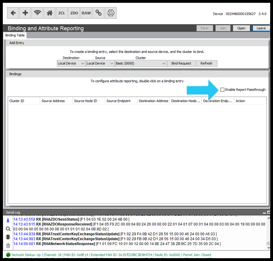
Step 1: Enable the Attribute Report Passthrough
- Open the RapidConnect Desktop instance.
- Click on the 'Binding' button
 .
. - Check the 'Enable Report Passthrough' checkbox. This will enable the Attribute Report Passthrough (PH:0x03, SH:0x26) command.
Step 2: Create a Binding
Bindings are used to configure a source and target of attribute reports and commands. In this case, the binding will tell our remote device where to send attribute reports when generated for a particular cluster. Follow the steps below to send the bind request.
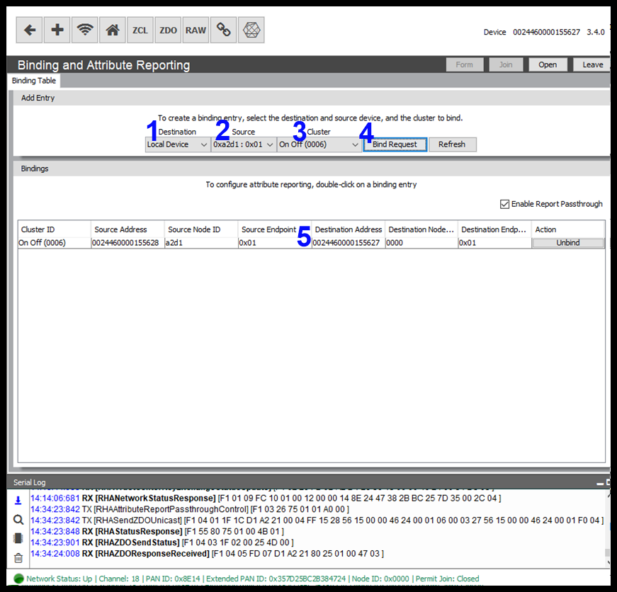
- Destination: Select a destination for the attribute report. In this case, the coordinator or Local Device.
- Source: Device the attribute will be reported from.
- Cluster: The cluster that the reported attribute is associated with.
- Bind Request: Click to send the bind request to the reporting device.
- Bindings: Shows the current device bindings.
Step 3: Configure Attribute Reporting
To access the attribute reporting window, double-click on the Binding entry of interest.Marked below with a blue arrow.
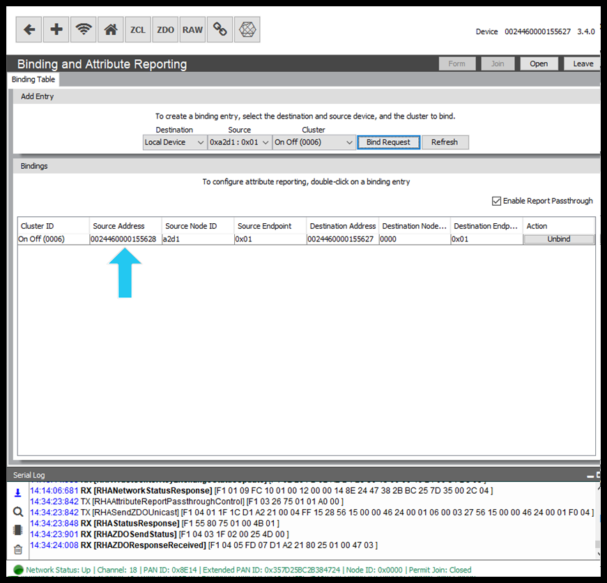
The attribute reporting window shows a list of reportable attributes for that specific cluster and binding instance.
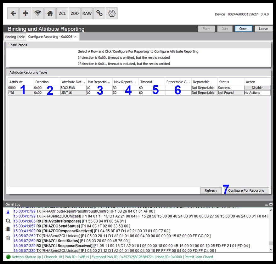
For the screenshot above you will see a single attribute is reportable for the On/Off cluster and that the status is 'Not Found' and we have not configured a report for this attribute.
The window components are outlined below:
- Reportable Attribute: Shows a configurable table that contains the necessary fields to send a Configure Attribute command.
- Direction: The direction field specifies whether values of the attribute are to be reported, or whether reports of the attribute are to be received. 0x00 = Sending a Report, 0x01 = Expect to receive a report.
- Min Reporting Interval: Specifies the minimum interval, in seconds, between issuing reports of the specified attribute.
- Max Reporting Interval: Specifies the maximum interval, in seconds, between issuing reports of the specified attribute.
- If the Maximum Reporting Interval is set to 0x0000, there is no periodic reporting, but change based reporting is still operational.
If the Maximum Reporting Interval is set to 0xffff, no reports shall be generated, whatever other conditions are satisfied.
- Timeout: Specifies the maximum expected time, in seconds, between received reports for the attribute specified in the attribute identifier field. If more time than this elapses between reports, this may be an indication that there is a problem with reporting. Only included when configuring for an expected incoming report.
- Reportable Change: The reportable change field shall contain the minimum change to the attribute that will result in a report being issued. Omitted for attributes with a 'Discrete' data type, e.g. Integers.
- Configure For Reporting: Sends the request to the relevant device.
Once the report configuration has been processed by the reporting device, the 'Status' will change to "Success" (1)
Periodic reports will be generated, and on receipt, will passed up from the Module to Host wrapped in a RHAZCLPassthroughMessage, as seen below (2).
.png?version=1&modificationDate=1571844071156&cacheVersion=1&api=v2&width=665&height=400)
Filter by label
There are no items with the selected labels at this time.
Legal Notices
Copyright © 2020 MMB Networks, Inc. All rights reserved.
Confidential materials prepared and delivered by MMB Networks for receipt and review only by any partner subject to a valid and enforceable MMB Networks confidentiality agreement. Any receipt, review, or misuse of any of the content exchanged hereunder by any party not a party to this confidential exchange shall be subject to any and all rights available under the law. All rights, title and interest to the materials shall remain with MMB Networks.
Any suggestions provided to MMB Networks with respect to MMB Networks' products or services shall be collectively deemed “Feedback.” You, on behalf of yourself, or if you are providing Feedback on behalf of your employer or another entity, represent and warrant that you have full legal authority to bind such entity to these terms, agree to grant and hereby grant to MMB Networks a nonexclusive, perpetual, irrevocable, royalty free, worldwide license to use and otherwise exploit such Feedback within any MMB Networks products and services.