Step 2: Network Configuration
A) Form Network
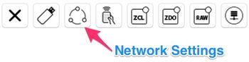
After completing Step 1: Hardware Configuration, return to the RapidConnect Desktop instance for the Combined Interface Coordinator and go to the Network Settings page.
This guide will assume that default values are used for the APS Link Key parameters and the 'Auto' options are checked for PAN ID and Extended PAN ID.
The 'Auto' options will generate random values for both PANID and Extended PAN ID.
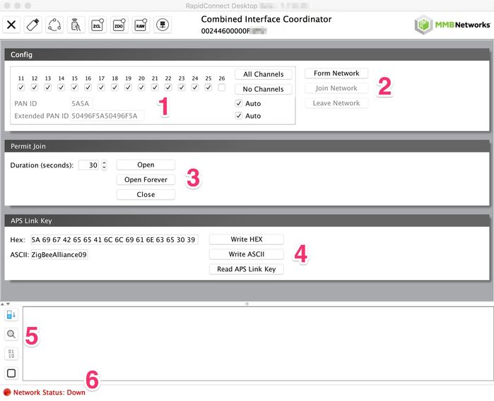
The Network Settings page shows the following components:
- Network Configuration Parameters
- Network Actions
- Permit Join Window
- APS Link Key Parameters
- Serial Log Viewer
- Network Status
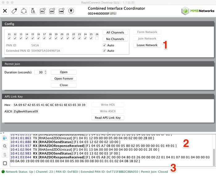
To form a zigbee network, click the ‘Form Network’ button. RapidConnect Desktop will send the necessary commands to the RapidConnect device to prompt it to form a zigbee network with the selected parameters. If multiple channels are selected, the channel with the least RF traffic will be chosen. Alternatively, the user can select a specific channel on which to form a network.
Once network forming is complete, RapidConnect Desktop will enable the 'Leave Network' button (1) and show the new network status and network information (3). The Serial Log Viewer will also be populated with serial messages sent between the Host (RapidConnect Desktop) and the device (2).
B) Join Network
It is now time to enable devices to join the newly formed zigbee network and then prompt the Dimmable Light to join.
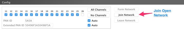
Go to the RapidConnect desktop instance that interfaces to the Combined Interface Coordinator. From here, open the Network Settings window from the top menu bar. Go to the Permit Join area and set a duration (e.g. 60 seconds). Click the ‘Open’ button.
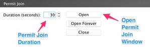
The ‘Open Forever’ button will open the permit join window for 248 seconds. Once that duration elapses, the permit join duration will automatically reset to 248 seconds, repeating indefinitely. MMB does not recommend using this setting in an environment with many zigbee devices, as it may lead to unintended devices joining the network. If using this setting, remember to use the ‘Close’ button to set the permit join duration to 0 after all intended devices have joined.
Once the permit join window is open, switch to the RapidConnect Desktop instance for the Dimmable Light device. Open the ‘Network Settings’ window from the menu.
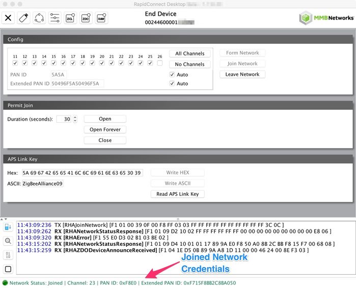
Once the Network Settings window is open, click the ‘Join Network’ button to initialize the joining process.
The Serial Log Viewer will show the frames being sent to and from the RapidConnect device over USB. Once the Dimmable Light device joins a network, the Network Status (shown at the bottom of the screen) will be updated and the network configuration will reflect the information of the joined network.
Next Steps
You can now move on to Step 3: Lighting Device Control Example.
Legal Notices
Copyright © 2020 MMB Networks, Inc. All rights reserved.
Confidential materials prepared and delivered by MMB Networks for receipt and review only by any partner subject to a valid and enforceable MMB Networks confidentiality agreement. Any receipt, review, or misuse of any of the content exchanged hereunder by any party not a party to this confidential exchange shall be subject to any and all rights available under the law. All rights, title and interest to the materials shall remain with MMB Networks.
Any suggestions provided to MMB Networks with respect to MMB Networks' products or services shall be collectively deemed “Feedback.” You, on behalf of yourself, or if you are providing Feedback on behalf of your employer or another entity, represent and warrant that you have full legal authority to bind such entity to these terms, agree to grant and hereby grant to MMB Networks a nonexclusive, perpetual, irrevocable, royalty free, worldwide license to use and otherwise exploit such Feedback within any MMB Networks products and services.